Monitoring the I/O Ports
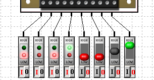
The IO-ports can be monitored and controlled via connected external components, e.g. digital I/O-components shown in figure 3. These components have two different modes. They can be used as active switches supporting HIGH, LOW and in certain configurations even high impedance values. The second mode is only passive. Here, the components are working as indicators showing the state of a channel by different LEDs.

Figure 3: Digital I/O-components connected to a device
Monitoring any ports or connections in the simulation is possible by using probes. A probe is a display component that can be attached to a connection or a port. Three different kinds of probes can be chosen using the menu bar on the left.

Figure 4: Different probes are available in the menu bar on the left
If you would like to set a probe select the desired menu item. Then, click on the connection or port you want to attach the probe to. A small window will appear showing the correspoding probe component. The following figures show some examples for different probes.

Figure 5: Text-Probe
The Text-Probe is used to display the state in a textual way. The display depends on the type of the port (digital, analog, etc).

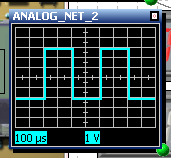
Figure 6: Scope-Probe
The Scope-Probe represents an oscilloscope. It should be used for frequently changing analog or pulsed signals.

Figure 7: Voltage-Probe
The Voltage-Probe is a simulated digital voltage meter. It displays the current voltage of the port it is attached to.

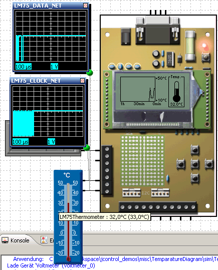
Figure 8: Example of a simulation with two Scope-Probes connected to the I²C bus
The example shows a simulation environment with an LM75 temperature sensor conntected to the I²B bus of a SmartDisplay Evaluation Board. The I²C bus is monitored using two Scope-Probes.